|
Stacker and
bucket wheel reclaimer could be in whole or partial
luffing style when applying hydraulic cylinders to drive the luffing
system. The whole luffing style is the slewing platform set with two
pivots to support the whole luffing system, in addition one or two
cylinders connecting the slewing platform and the hoisting system to
adjust the luffing angle. In the course of luffing , the rotating angles
around the axis of the two pivots on the slewing platform for any parts of
the general luffing system, such as the bucket wheel, boom and
counter-weight etc. are equal, meaning that the upper part is a whole part
rotating around the two pivots. For common styles of whole luffing system
see fig 1. and fig 2.
In the course of using and maintenance, the users need
to know and master the position as well as the changing law of gravity
center of the whole machine or the luffing system so as to keep routine
maintenance, due to various kinds of reasons. The position as well as the
changing law of gravity center of the general luffing system could be
known by means of measuring then calculation.
1. The measurement upon unbalanced torque
The unbalanced torque which is the product of the
distance between the gravity center of the hoisting system and the axis of
the two pivots on the slewing platform and the total weight of the
hoisting system, could be got by means of measuring the balanced-to-ground
force at the bucket wheel or the pressure of the cylinder and then
calculation.
1.1 Measuring the unbalanced torque by means of testing
the balanced-to-ground force at the bucket wheel.
Applying instruments such as automobile crane,
electronic scale for weight etc. to measure the balanced-to-ground forces
at the bucket wheel in two different luffing angles. Seeing fig 3.
Testing condition: within the range of the luffing
angles for test, the position of the gravity center of the luffing system
must be at the front of the axis of the two pivots on the slewing platform
all the time, preventing from overturning back; the cylinder must be off
the luffing system; the balanced-to-ground forces tested at the bucket
wheel must be over zero.
After measuring, the unbalanced torque:
M1=N1R1 (1)β=α1, if
α1=0
?nbsp; ( horizontal)
M2=N2R2 (2)β=α2
Explanation: β-----------------the luffing
angles α1, α2, ?
M1, M2----- the unbalanced torques
corresponding toα1, α2, kN.m;
N1, N2------------ the unbalanced-to-ground
forces at the bucket wheel
corresponding toα1, α2, kN ;
R1, R2------------ the distances in
horizontal from N1, N2 to the axis of the two pivots, m;
1.2 Measuring the unbalanced torque by
means of testing the pressure of the hydraulic cylinder.
Applying pressure gauge with high precision
or digital pressure gauge to test pressure (Pa1, Pb1,
Pa2, Pb2) on the
piston side and piston rod side of cylinder respectively.
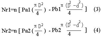
Calculating the force on the cylinder:
Explanation: D-----------------the diameter
of piston, m;
d-----------------the diameter of piston
rod, m;
Pa1--------------the pressure on the piston
side of cylinder
at the luffing angle α1,kPa;
Pb1--------------the pressure on the piston
rod side of cylinder
at the luffing angle α1, kPa;
Pa2-----the pressure on the piston
side of cylinder at the luffing angle α2, kPa;
Pb2-----the pressure on the piston
rod side of cylinder at the luffing angle α2, kPa;
Nr1, Nr2--------the total force on one or
two hydraulic cylinders at the hoisting angle α1 orα2 ,
kN;
when Nr1 > 0 or Nr2 > 0 , the
hydraulic cylinder is pushed;
when Nr1 < 0 or Nr2 < 0 , the
hydraulic cylinder is pulled;
n----------------the number of the
hydraulic cylinder
Calculating the unbalanced torque:
M1=Nr1.R1 (5) β=α1, if:α1=0?horizontal)
M2=Nr2.R2 (6) β=α2,
Explanation:
M1, M2 are the unbalanced torques at the
luffing angleα1 orα2 respectively, kN.m;
Nr1, Nr2 are the force on one or two
hydraulic cylinders at the luffing angleα1 orα2 respectively,
kN;
R1, R2 are the distances from the axis of
the two pivots of the luffing system to the axis of the piston rod at the
luffing angleα1 orα2 respectively, m;
2. Calculation on the position of the
gravity center of the luffing system
After measuring the unbalanced torque,
according to two luffing angles α1 andα2 as well as corresponding M1,
M2, the position of gravity center is calculated. This gravity center of
luffing system is the relevant coordinate position corresponding to the
axis of the two pivots on the slewing platform at the hoisting angle 0?
Fig 5. is sketch for calculating the
gravity center. The coordinate origin ‘o?is the axis of the
two pivots supporting the luffing system, angle α1 andα2
are the luffing angles of two positions at the time of luffing down
respectively, presuming C the gravity center of luffing system, rotating
radium around point ‘o?r, the angle from the line connecting
‘c?and ‘o?to X axis φ. After changing the
luffing angle, the angles from the line connecting gravity center ‘c?
and the coordinate origin ‘o?to X axis are φ-α1
andφ-α2 respectively.
From the static balance relationship:
M1=Grgcos(φ-α1) (7)
M2=Grgcos(φ-α2) (8)
Explanation:
G------the total mass of the luffing
system, t;
r-------the rotating radium when the
gravity center luffing, m;
g------the gravity acceleration, 9.81m/s2;
(7) divided by (8):
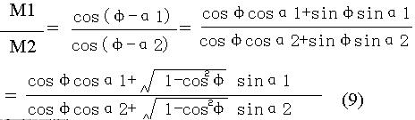
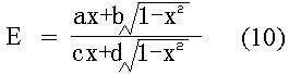
If :E=M1/M2,X=cosφ,a=cosα1
, b= sinα1,c= cosα2,d= sinα2;
inserting formula(9):
clearing up:
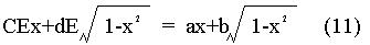
moving items:
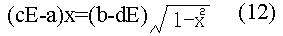
squaring the two sides of the equation:
((cE-a)2x2=(b-dE)2(1-x2) (13)
moving items:
[(cE-a)2+ (b-dE)2
]x2 = (b-dE)2 (14)
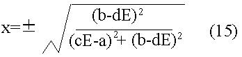
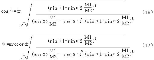
inserting the original each variable into formula(15):
when gravity center luffing, the rotating radium around point ‘o?
is:
r=M1/(Ggcos(φ-α1)) (18)
the coordinate of gravity center of the hoisting system (horizontal)
is:
xc=rcos(φ) (19)
yc=rsin(φ) (20)
3. The changing law on the gravity center of the luffing system
The position of the gravity center of the luffing system changes in
accordance with the luffing angles, the changing law:
xc=rcos(φ+α) (21)
yc=rsin(φ+α) (22)
explanation: α-------------- the luffing angles, at luffing up, α>0?/p>
at luffing down, α<0?/p>
at level, α=0?/p>
4.The significance of calculating the position as well as the changing
law of gravity center of the luffing system:
a. Analyzing the changing law of force on the cylinder within the whole
range of luffing angles furthermore.
b. Analyzing the stability of the whole machine as well as the state of
traveling wheel pressure furthermore.
c. Offering the basis of load changing at different luffing angles for
people maintaining the equipment with enough knowledge on it, avoiding
fault in work.
By liyimin 18 July
,2000
本文中文版被他人剽窃发表到国内重要杂志上
本文为经过实践撰写的稿件2000年发表在企业刊物上,在万方数据上可以找到。后来被他人剽窃发表到国内重要杂志上。
|